Indication of surface texture
on technical drawings
Technical drawings describe mechanical workpieces to be produced, their dimensions and geometry, and their fabrication tolerances. They use a standardized graphical language, that allows subcontractors to understand the designer's intent and produce compliant workpieces. The technical drawing is even sometimes a contract binding the parties, that acts as a reference in case of disputes about non compliance of the production. Besides dimensional specifications and tolerances, one may find surface texture specifications, indicated using the root symbol. This root symbol is defined in the ISO 1302:2002 standard, which was recently replaced by ISO 21920-1:2021. It must contain, at least, the name of the specified parameter and its limit value. Other complementary indications are possible, and have to be placed at particular locations below or around the root symbol. Moreover, many default indications are implicit and do not need to be written on the drawing.
1. Specification using the root symbol
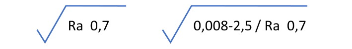
The only correct place to indicate a parameter is under the root symbol. The minimum indication is the name of the parameter and its limit value (see below on the left). Many other indications are defined by default and can be omitted. When values are required, other than the defaults, they must be written explicitely. For example, below, on the right, the bandwidth is defined with a cut-off of 8 µm for λs, and a cut-off of 2,5 mm for λc.
The ISO 1302 stndard from 2002 describes all the possible indications on a technical drawing and their position, regarding surface texture tolerancing.
2. Obsolete indications
The ISO 1302 standard has evolved since its first version in the 1970s, and several practices are now obsolete and should not be used anymore on modern drawings. This is why, users should be cautious with books that are quite old because they are not compliant anymore with current rules.
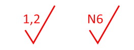
Here, two examples of obsolete notations, where the limit was indicated on the left of the root symbol. It was even possible to use classes (here N6). The Ra parameter was the default parameter and therefore was omitted.
These notations should not be used on drawings after 2002.
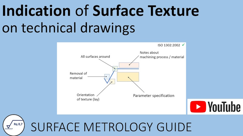
3. Position of indications under and around the root symbol
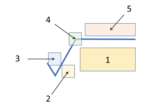
1. The specification string is placed below the root symbol. This string is coded precisely (see below)
2. The orientation of texture lay is noted at the bottom right of the triangle.
3. Constraints regarding material removal are noted above the triangle.
4. A symbol placed here extends the specification for all surfaces around the projection plan.
5. Complementary information on machining or materials can be placed above the horizontal bar.
4. Specification string under the root symbol
In the standardized specification string, when a term corresponds to a default value, it can be omitted. But it still needs to be taken into account during verification.
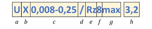
a) The first term is the type of tolerance. Is the limit value a max or min value? If this term is omitted, it means that it is an upper tolerance (symbol U). In the case of a lower tolerance, it is noted L.
b) The second term allows to specify a particular filter type. By default, it is the Gaussian filter (G) for most parameters. Several other letters are defined for other filter types, if necessary. The most common are RG for Robust Gaussian, and S for spline.
c) The third term is important. It specifies the filter bandwidth, with the microroughness cut-off λs, and the main cut-off λc for roughness and waviness parameters. The default values are 2,5 µm for λs and 0,8 mm for λc (see ISO 4288)
d) Then a separation bar is inserted, unless all previous terms are omitted.
e) After the separation bar, the parameter name is noted, with a P prefix for a primary profile, a R prefix for a roughness profile, and a W prefix for a waviness profile.
f) In some cases, when the parameter needs to be calculated on a different evaluation length than the default length, the multiple of sampling lengths (λc) is noted right after the parameter. This practice is pretty rare but is can be sometimes seen on drawings.
g) The decision rule that changes the way limits are interpreted is, by default (ISO 4288), the 16 % rule. It is explained in details below. If the Max rule needs to be used, then it can noted after the parameter.
h) Finally, the tolerance limit is noted, without units. The unit is deduced from the specified parameter. For example, µm for height parameters, mm for RSm, % for Rmr, etc.
Indication of surface texture on technical drawings
This video introduces the graphical language used to indicate surface texture specifications on technical drawings, according to ISO 1302. Changes introduced by the new ISO 21920-1 are also discussed.
Duration: 15 min 04 [Fully in English]
5. Orientation of texture lay
At the foot of root symbol, on the right of the triangle, it is possible to specify the texture lay. Some machining methods leave a signature on the texture with oriented scratches and grooves.
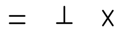
The most common are parallel, perpendicular or crossed grooves, with respect to the projection plan.
Other possibilities also exist: M for multidirectional, C for circular, R for radial and P for particular.
6. Material removal
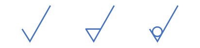
The triangle can be open or closed, or have a circle, to specify a particular constraint regarding material removal during machining.
An open triangle does not give any constraint. A closed triangle requires material removal during machining. A circle forbids material removal.
7. All surfaces around
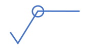
When the specification applies on all surfaces around a workpiece, the symbol just needs to have a circle at the corner between the horizontal and oblique bars. It simplifies the drawing as a single indication applies on many surfaces.
8. Complementary notes
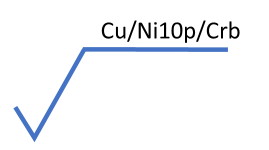
Additionnal information can be written above the horizontal bar, to express constraints on material or machining.
9. Position on a drawing
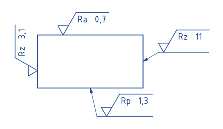
The root symbol is placed on a drawing, with the tip of the triangle in contact with the surface, including on vertical faces (it has to be rotated to the left then).
The root symbol can also be placed on a dimension lead line, as long as it stays readable. Other options are available, and in particular, a simplified writing (see in the video).
10. 16% rule
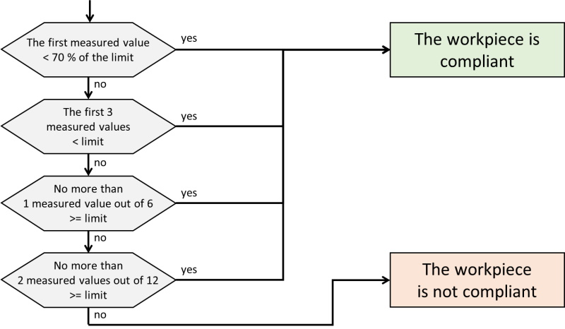
Using the 16% rule requires a series of tests, as described in the annex of ISO 4288. However, this rule is often hardly understood or correctly applied.
The main issue is that, for the designer, the specified tolerance limit is a limit not to cross. But the 16% rule allows the metrologist to accept up to 1/6 of bad measurements! Especially, when allowing one value above the limit out of 6, this value may be way out of range, leading to quality problems in practice.
In addition, the method may require a large number of measurements, which is not very economically efficient. And this rule is not really compatible with capability procedures, nor with decision rules described in ISO 14253.
In the new ISO 21920-1 standard, the 16% rule is not the default rule anymore. It is replaced by the Max rule, which is simpler and more logical. This new standard was published in December 2021 and is now an official replacement of ISO 1302.