Leveling and form removal
The ISO 3274 standard specifies that the primary profile should not contain the nominal form of the workpiece. The form component must be removed prior to any other metrological operation. With an areal measurement, the production of a S-F surface requires the application of an F Operator. When the form is just a line segment or a plane, this operation is called leveling. When the form is non planar, it is called form removal. This page introduces the different methods that can be applied and discusses their applications.
1. Nominal form
The Nominal form is a geometric form intended by the designer of the mechanical workpiece. Usually it is a planar form or a rotary form (cylinder, cone, sphere). Specifications of surface texture are made on a flat surface, regardless of the original geometrical form, so the metrologist must apply an operation to flatten the profile or the surface before carrying out the metrological analysis. This operation consists in modelling the shape and associating it with to the cloud of measured points in order to subtract the form.
In the case of a non-manufactured object, there is no nominal form, but it can still be useful to remove the natural form using a polynomial fit or a filter.
Surface texture parameters depend on a reference (mean line or mean plane) used in the detection of peaks and valleys, or on the calculation of mean values and moments. Form removal and leveling make it possible to define this reference.
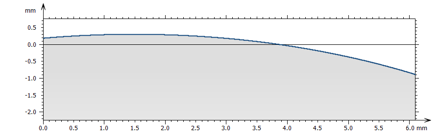
Above: profile measured on a sphere ; below, the profile, after a circular form removal (least-square circle, calculated radius of 9.53 mm)
2. Internal reference of instruments
On a 2D contact profilometer, the scanning axis along X gives the reference and defines the origin of heights. This reference is usually provided by a high precision steel rod on which pads are sliding to move the sensor and the stylus during the scanning. Any straightness deviation from this reference is injected into the measured profile as a height bias. Some profilometers can calibrate this straightness deviation by measuring a reference glass flat and saving a straightness profile that is then subtracted from any subsequent measurement. Once the leveling or the form removal is done on the profile or on the surface, the user can analyze form deviation, waviness and/or roughness.
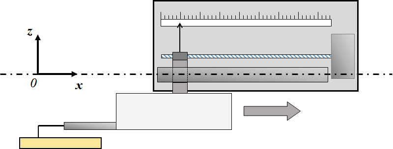
Diagram of a 2D contact profilometer and its coordinate system.
With a 3D optical profiler, the reference depends on the optical technology. In the case of a vertical scanning device, the alignment and linearity of this device influence the reference. The reference mirror of an interferometer also influences the height reference. In general, any disturbance is mapped during a calibration routine done in the factory, or sometimes by users. See also ISO 25178-700.
Skidded stylus
Workshop profilometers usually do not have an internal reference but they use a skid that will follow the form and allow the stylus to record height variations with respect to the skid. Therefore the measured profile contains only the shortest wavelengths.
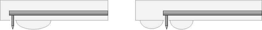
Two examples of skids for workshop profilometers
Profilometers equipped with skids cannot evaluate waviness, unless they use special wide skids. Such profilometers are usually dedicated to roughness parameters.
3. Manual leveling and alignment
The metrologist should align the workpiece with measurement axes as closely as possible. For example, on a contact profilometer, the sample is positionned as horizontally as possible, aligned along the X axis, which is itself aligned on the internal reference of the instrument. This guarantees that heights are correctly recorded along the Z axis of the instrument which is very close to the Z axis of the workpiece. The leveling operation then subtracts the remaining fractions of degrees of the residual slope.
When measuring a surface, for example with a confocal microscope, the sample will be placed horizontally to ensure that the vertical scanning axis is as perpendicular as possible to the sample plane.
Corrections carried out by the analysis software will be more efficient and precise if the sample is physically aligned and leveled on the instrument.
4. Reference line and reference plane
On a profile, the reference line is defined by the leveling or the form removal, and therefore depends on the association method. By default, the least squares line is associated with the profile. It becomes the horizontal reference of the primary profile, and defines the origin of heights.
Similarly on a surface, the mean plane is calculated by the F Operator. Local structures and geometrical features may affect this reference by deviating the associated plane.
5. Association
Association is an operation that configures a mathematical model in order to best fit a real workpiece, usually represented by a cloud of points. Models are geometrical forms (line, plane, portion of a sphere, of a cylinder, of a cone, polynomial, etc.).
Association methods used in surface texture metrology are:
- Least squares, simple or total, constrained or not;
- Minimum zone;
Least squares corresponds to the L2-norm as they minimize quadratic deviations. Minimum zone corresponds to the L∞-norm also called Chebychev. The L1-norm is sometimes used by minimizing absolute values of heights or simply averaging heights.
Constraints used in association may fix the radius of a sphere and allow the position of the center to be calculated, or may shift the least squares plane outside the material, i.e. shifted in contact with the highest point of the surface.
Symbols used in association for least-squares are LSLI (for a line) or LSPL (for a plane).
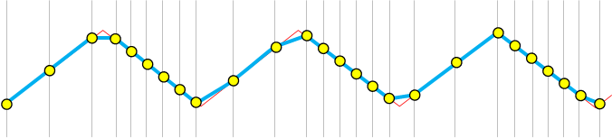
The Minimum Zone method encloses the profile between two parallel lines, or the surface between two parallel planes, and tries to find the best orientation that minimizes the distance between the two lines (or two planes). Symboles for Minimum Zone association are MZLI and MZPL.
6. Deviation along z or along the surface normal
The slope of a profile or a surface is usually very small, barely a few degrees, so it is common to subtract heights between the profile and the calculated line. But in the case of a larger slope, the subtraction introduces a significant error and may also deform the profile.
Subtraction of the reference line along the Z axis.
Leveled profile. The shape is modified by the subtraction due to the large slope.
In the case of a large slope it is recommended to rotate the profile until it reaches the horizontal position. It is the equivalent of subtracting heights with respect to the normal vector of the nominal form. The shape of the profile is not altered but the spacing of the points is no longer constant. This implies a subsequent resampling which introduces a smoothing of the highest frequencies (noise). In some cases, overhangs may appear and are eliminated during the resampling. Or it may require the handling of irregularly spaced profiles, also called parametric profiles, (x, y) = f(t).
Subtraction of the reference line along the normal.
Leveled profile. The shape is respected but points are not equally spaced.
7. Association methods
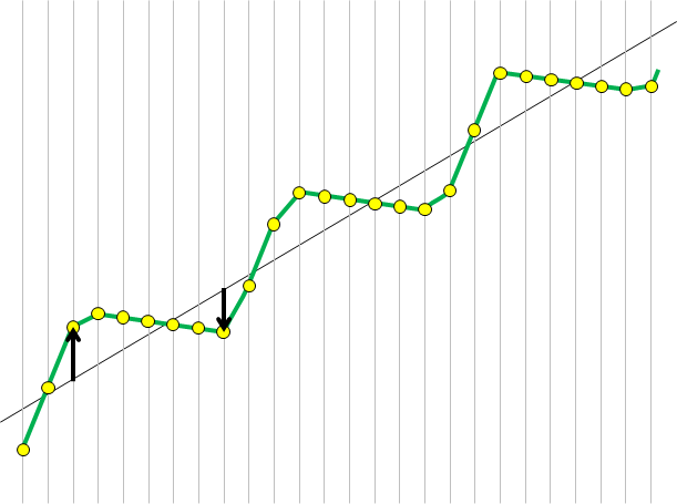
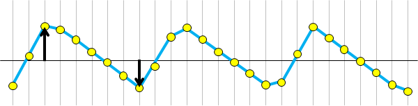
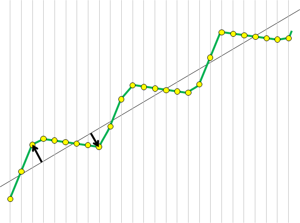
The default association method for surface texture metrology is the least-squares association. This is the best method if surface texture is globally random (stochastic), without structure or geometrical shapes. However, if the surface contains periodic features or geometrical structures, the least-squares method can be severely altered by the irregular distribution of heights.
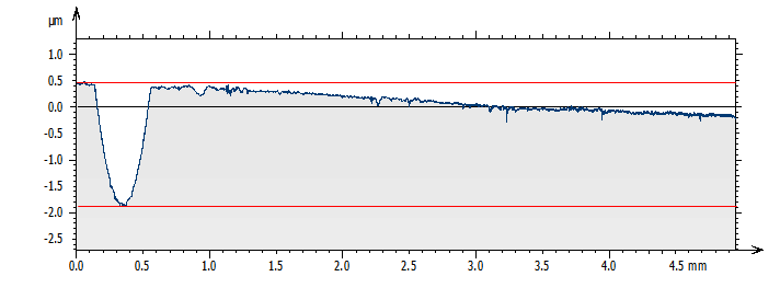
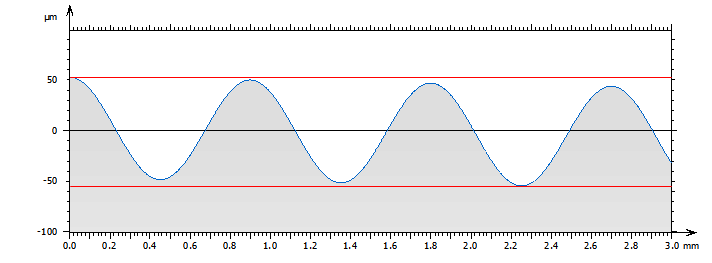
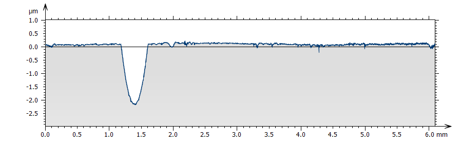
Above, the least squares line is disturbed by the shape of the profile: Top profile, because of the groove. Bottom profile, because of the distribution of heights, higher on the left and lower on the right. In these cases, a leveling using the Minimum Zone method is preferable as it provides the correct principal direction of the profile. On the top profile, it would also have been possible to exclude the groove portion from the calculation of the least squares line.
8. Exclusion of structures
Exclusion of structures can be manual or automatic, and allow the calculation to take into account only a subset of points of the profile or the surface when estimating the nominal form.
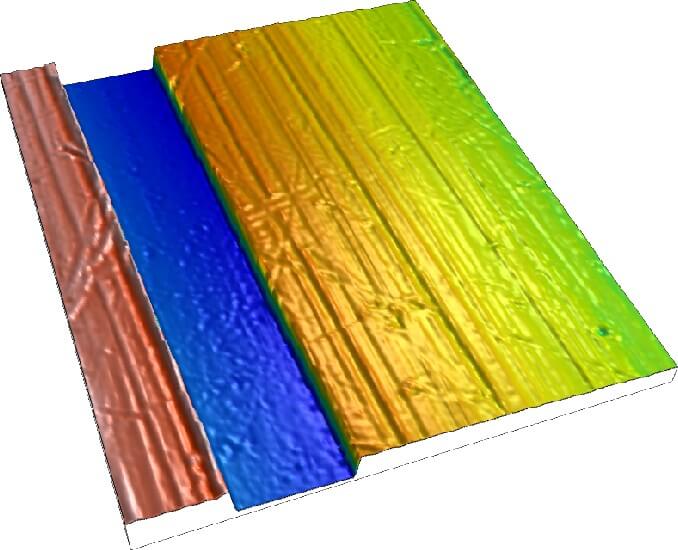
In the case of this surface, the groove is not centered and it alters the calculation of the least squares plane, leading to an incorrect leveling.

The solution consists in excluding the groove from the calculation by marking it with a selection tool in the dialog of the Leveling operator (or Form removal). The excluded area is marked in gray (on the left).
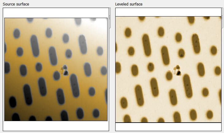
9. Automatic exclusion of structures
In other cases, structures can be automatically excluded.
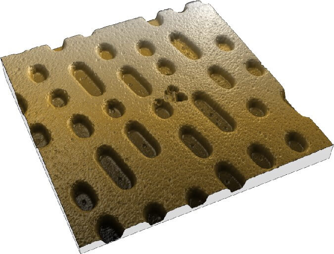
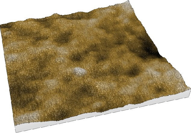
This surface of a DVD measured by an AFM contains too many dimples that would be inconvenient to exclude manually. Each cell influences the calculation of the least squares plane as its height is lower than the flat plane above, and the distribution of cells is not regular on the surface.
The automatic exclusion option can be configured to exclude structures below and/or above the mean plane.
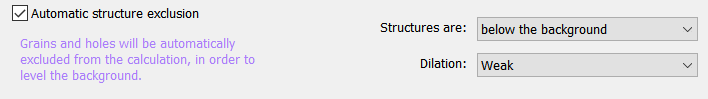
Here, structures are excluded and the least-squares plane is calculated correctly only from points on the flat plane above.
10. Leveling of complex form
In non-mechanical applications, for example, when measuring biological samples, or surfaces of archeological artefacts, it may be necessary to define a flat reference on sample that has a complex form. It is possible to estimate a polynomial shape, and optionally exclude a portion of the surface. Below, a wound measured on the skin of a patient; the form comes from the leg. Removing the form makes it possible to define a flat reference, calculate the volume of the wound and compare it to a later stage of healing.
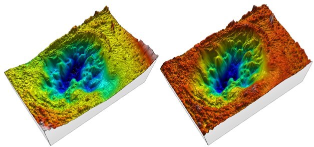
Polynomials however should be used with care because they usually tend to diverge on edges, especially with high order polynomials.
11. Line by line leveling
Some instruments that use lateral scanning, such as profilometers or AFMs, are occasionally affected by vertical shifts between lines. In the case of a profilometer, this is due to the straightness deviation of the Y axis. In the case of a scanning probe microscope, the metrological analysis of measurements cannot be done before such line by line leveling is carried out. This solution consists in leveling each line individually in order to align them on the same flat reference. It may be necessary to exclude some portions to avoid bias on the mean lines.
AFM image showing a vertical shift in two places
The surface leveled line by line, reveals the surface topography.
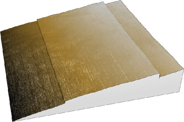
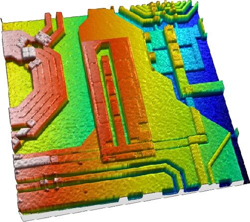
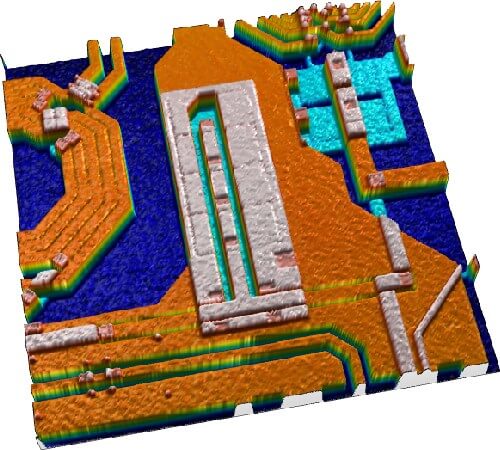
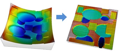
12. Multi-plane leveling
A surface with several planes at different heights may be leveled using the Partition and level operator that segments the surface using watersheds and pruning algorithms.
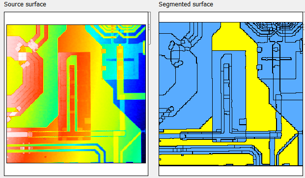
Above: the image on the right shows the segmented surface. This allows the user to click on the areas that will be used to calculate the least squares plane. The whole surface will then be leveled with reference to that plane.
An even more difficult case: when the different planes are affected by a general curvature that needs to be removed, for example in order to evaluate the step height between the planes. It is then necessary to use a special function, multi-plane leveling, where the algorithm will assess the curvature ignoring edges and heights.
13. Normative references
In addition to surface texture standards, it may be useful to consult the following documents:- ISO 1101 (2013) Geometrical Product Specifications (GPS) - Geometrical tolerancing - Tolerances of form, orientation, location and run-out
- ISO 17450-1 (2012) Geometric Product Specifications (GPS) - General concepts - Part 1: Model for geometrical specification and verification
- ISO 17450-2 (2012) Geometric Product Specifications (GPS) - General concepts - Part 2: Basic tenets, specifications, operators, uncertainties and ambiguities
- ISO 22432 (2012) Geometric Product Specifications (GPS) - Features utilized in specification and verification